Revolve is a function that allows the user to extrude a closed profile around a fixed axis up to 360°. The axis can be part of the profile, an existing edge on a part, or one of the axes of the Cartesian coordinate grid. Grid axes may be selected from the Origin folder located in the Browser bar. Open the file called Bushing. Use the revolve function to revolve the sketch around the existing axis a full 360°.
Cirrcular Pattern
pattern function allows the user to make multiple copies of an existing feature in one of three ways. A circular pattern is often used to array a hole around a center axis. An edge on an existing feature can also serve as the center axis. Open the file called Circular Pattern, and use the circular pattern function to copy the existing hole on the flange plate a total of 10 times (the first hole must be represented in the count) around the existing work axis.
Drilled Holes

The hole function requires a hole center for each instance. Open the file called Drilled Holes. The existing feature is a blind hole, and has been created for you. The following page shows the different function windows that are associated with a counterbore, countersink, threaded hole, and clearance hole. All hole centers in a sketch will be auto-selected by the computer when the hole command is initiated. You will have to hold down the shift key to deselect the hole centers that you do not want. Work your way around the block in a clockwise direction initiating the hole function, selecting the appropriate hole center, and identifying the type of hole feature that is needed. The counterbore will have a major diameter of .75 inch that is recessed .25 inch. From there, its through hole will have a diameter of .375 inch. The countersink has a major diameter of .75 inch, with a taper of 83°. Its through hole has a diameter of .375 inch. The threaded through hole has a nominal diameter of .25 inch, and a 1/4-20 thread applied to its interior wall. The clearance hole goes through the disc, and has a diameter of .531 inch. Note: a shared sketch will not disappear after the first feature is created.
Tappered Extrusions
Extruded objects can be given positive or negative taper angle. A common example of a tapered extrusion is the design of an ice cube. The sides of the ice cube are tapered with a draft angle to allow the cube to be easily removed from the ice cube tray. Open the file called Extrude-Taper, and extrude the square a distance of 1 inch with a taper angle of -10°.
Fillet and Chamfer
Intersect extrusions
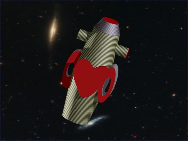
The intersect extrusion function will perform a Boolean addition and subtraction in one operation. Any part of the sketch profile that overlaps existing geometry will remain. The portion of the sketched profile and the existing geometry that do not overlap will be removed. Open the file called Intersect, and perform an intersect extrusion on the sketch all the way through the existing object to observe what takes place.
Loft
The loft function allows the user to create a solid or surface by blending two or more shapes that are located on different planes. Open the file called Loft. Use the loft function to blend the three profiles into one solid object.
Shell
The shell function allows the user to remove unnecessary mass from a feature. The resulting geometry will have a wall thickness that is specified by the user. Open the file called Lunch Tray. Rotate the object so that its underside is visible, as shown in Step #1. Use the shell function to pocket out the material on the bottom side of the object, leaving a wall thickness of .3125 inch, as shown in Step #2.
Sweep
The sweep function allows the user to extrude a closed profile along a path. The path may be open or closed. The profile and the path must exist as two separate sketches. Open the file called Paper Clip. Use the sweep function to extrude the circle along the existing path to create the form of a paper clip.
Some patterned features follow contoured paths. Open the file called Pattern along a Path. Use the rectangular pattern function to copy the existing rectangular extrusions 13 times along the curved path of the base feature.
The rectangular pattern function allows the user to make copies of an existing feature in one direction, or two directions simultaneously. Existing edges or the axes of the Cartesian coordinate grid must be selected to identify the desired direction(s). Open the file called Rectangular Pattern. Use the rectangular pattern to copy the existing cylindrical extrusion six times in the horizontal direction and four times in the vertical direction.
. A rib is a relatively thin flat member that acts as a brace support. It is also referred to as a web. The rib function allows the user to place such a support between two intersecting surfaces. Open the file called Rib Support. A line profile has been created on a work plane that exists midway through the object. Use the rib function to turn this line profile into a .125 inch support web between the two perpendicular surfaces.
The coil function allows the user to extrude a closed profile along a helical path and around an existing axis. The axis may be an existing edge, a sketched line, or a work axis. Open the Spring file. Use the coil function to turn the existing circle into a spring form by coiling it around the Y axis of the Cartesian coordinate grid. The Y axis must be selected from the origin folder in the browser bar. The spring will have a height of 6 inches and the circle will revolve around the Y axis a total of five times.

In Activity 1.4.2 Making Sketches in CAD, you used the sketch tools to insert a JPG graphic onto a sketch plane that was located tangent to the outside surface of a water bottle model, and saved the file to your student folder. Locate and open this file. Decal is a function that allows the user to place an image onto a model surface. This function requires a feature and sketch, such as the water bottle and the logo graphic pictured above. Graphics must be either JPG or BMP formats. Use the decal function to wrap the image around the surface of the water bottle.

In Activity 1.4.2 Making Sketches in CAD, you used the sketch tools to place your name on a sketch plane that was located tangent to the outside surface of a wrist band model, and saved the file to your student folder. Locate and open this file. Emboss is a function that allows the user to raise a design from a surface, or carve a design into a surface. This function requires a feature and a profile, such as the wrist band and text. Use the emboss function to project the text down onto the surface of the wrist band, and extrude the letters a distance of .02 inch.
Threaded Rod
The thread function allows the user to simulate the appearance of threads on the curved surface of either a cylinder or a hole. The diameter of the cylinder or hole must match the nominal diameter of the desired thread form. I Opened the file called Threaded Rod. Use the thread function to place a right-hand 5/8-11 UNC thread along the entire length of the cylinder’s curved face.
Emboss
Decal
Coil
Rib
Rectangular Pattern
Rectangular Pattern along a Path
Fillet is a function that allows the user to create a rounded blend where two surfaces meet to form an edge. It should be noted that on an exterior corner, the resulting feature is known as a round. On an interior corner, the resulting feature is known as a fillet. Open the file called Fillets Chamfers. Use the fillet function to apply a .25 radius to the corners shown above. This model will be used in the next exercise.Chamfer is a function that allows the user to apply an angle surface where two existing surfaces meet to form an edge. Use the chamfer function to apply a .25 inch x 45° chamfer to the edges shown above.


